
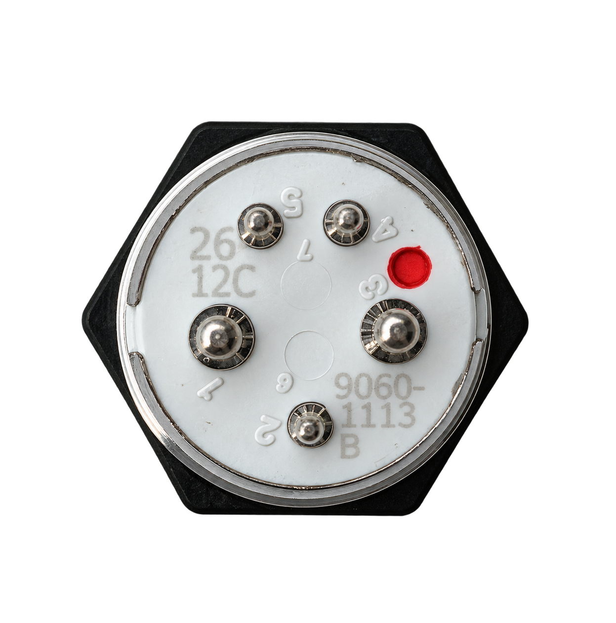
9060-1113
OFF/ON
Red identification dot
Customer wiring reference
Choose the switch function and the plug wiring diagram independently, then view both selections together. The molded cavity numbers are the position reference, even when the harness is rotated.
Selected switch
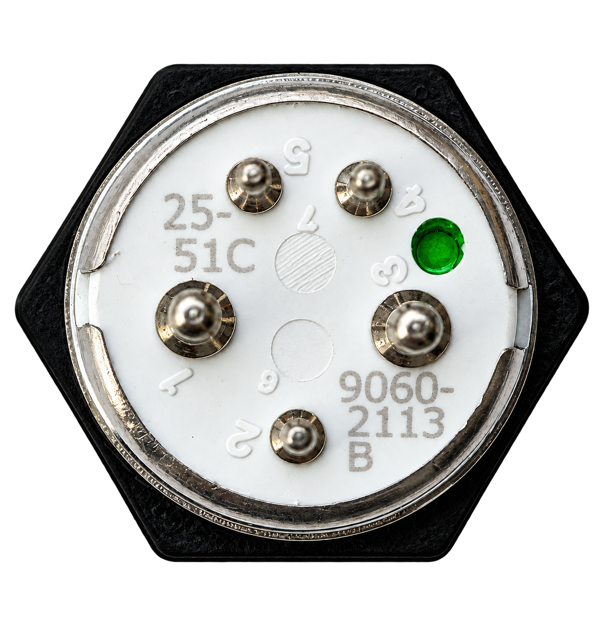
(ON) indicates a momentary function.
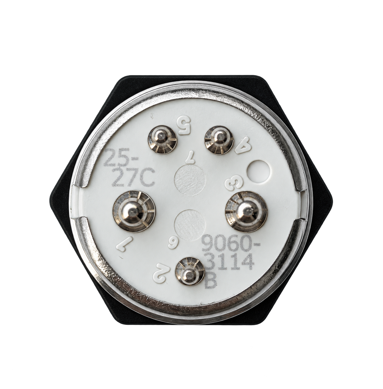
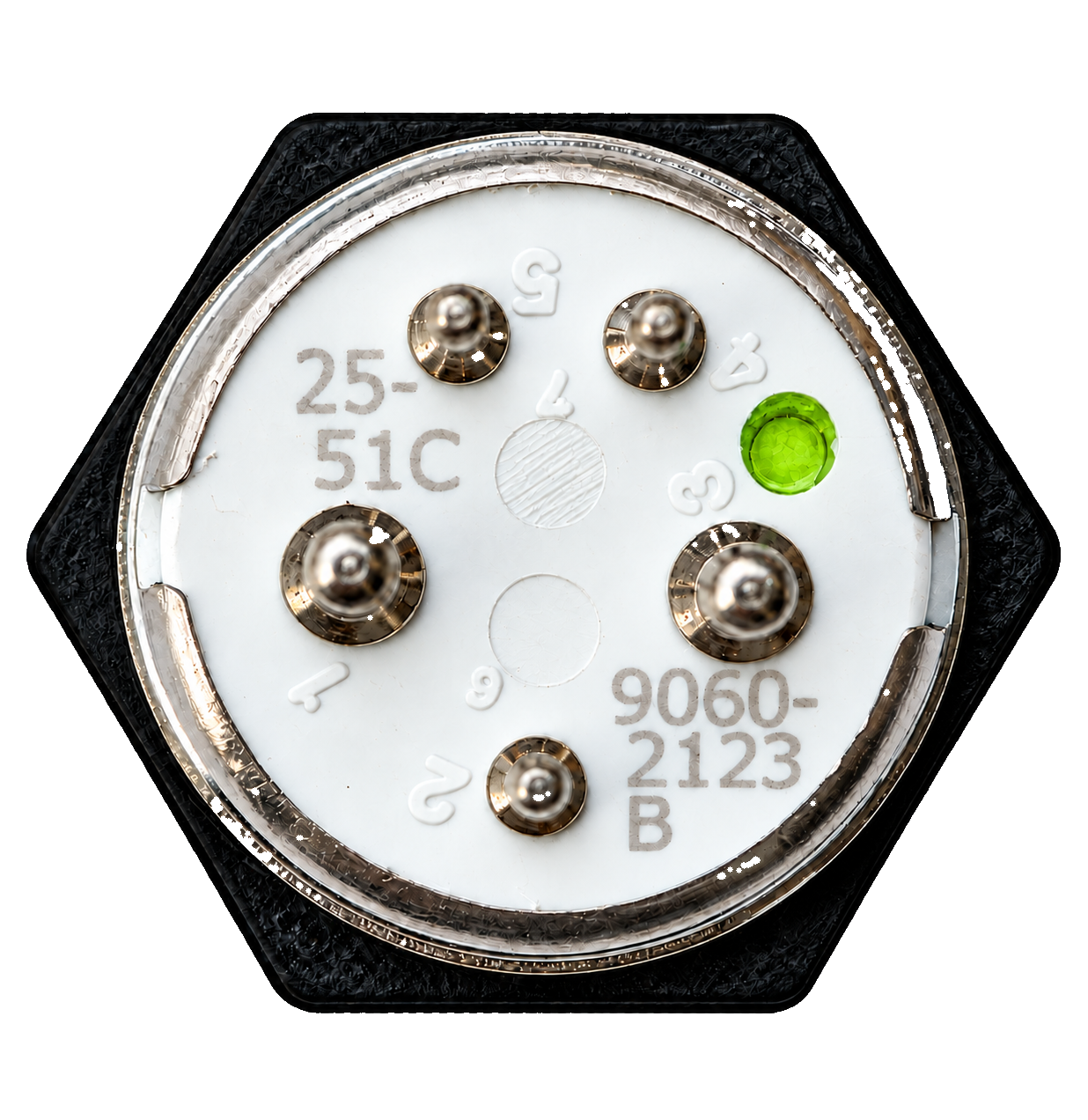
Both (ON) positions are momentary.
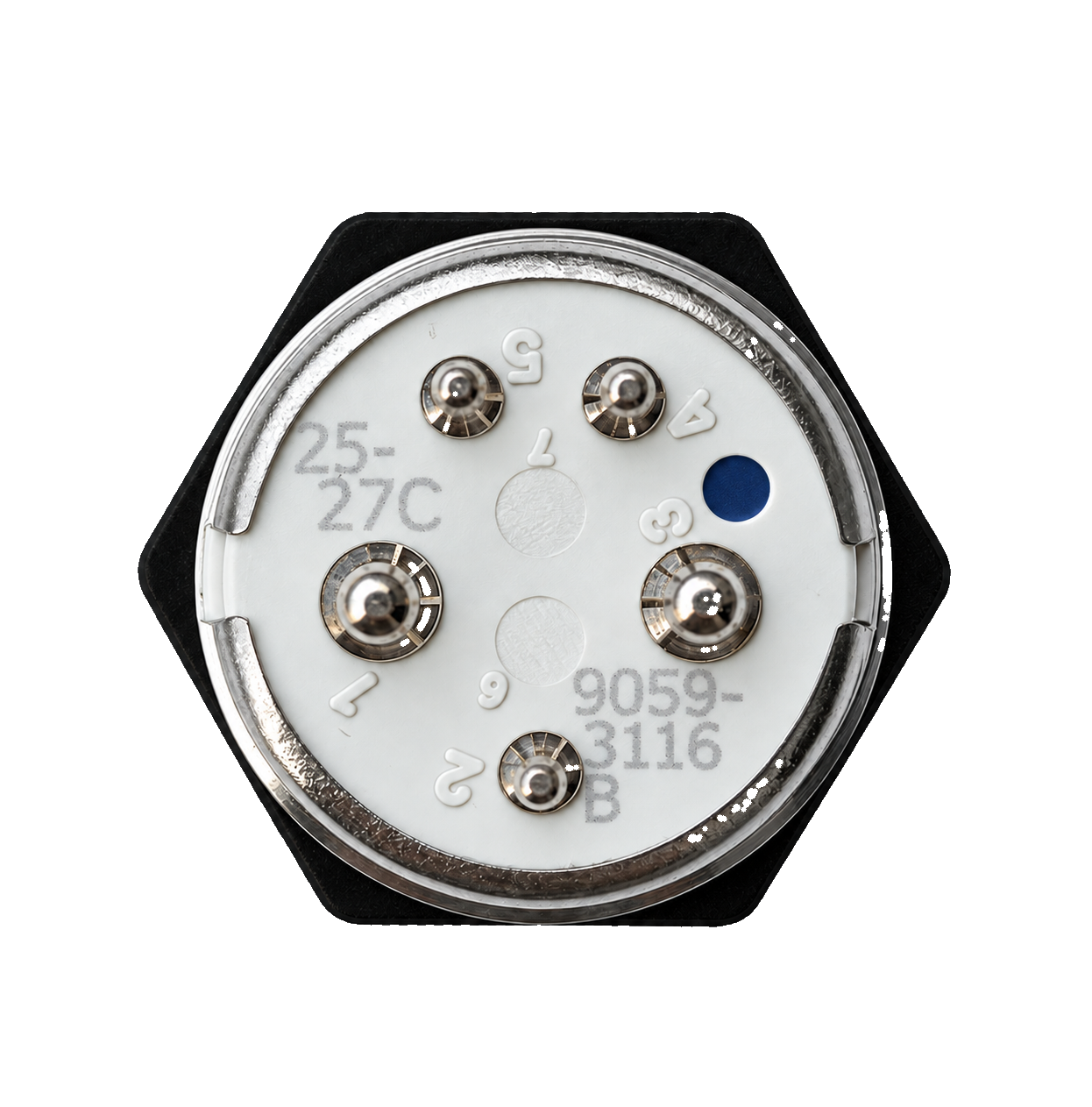
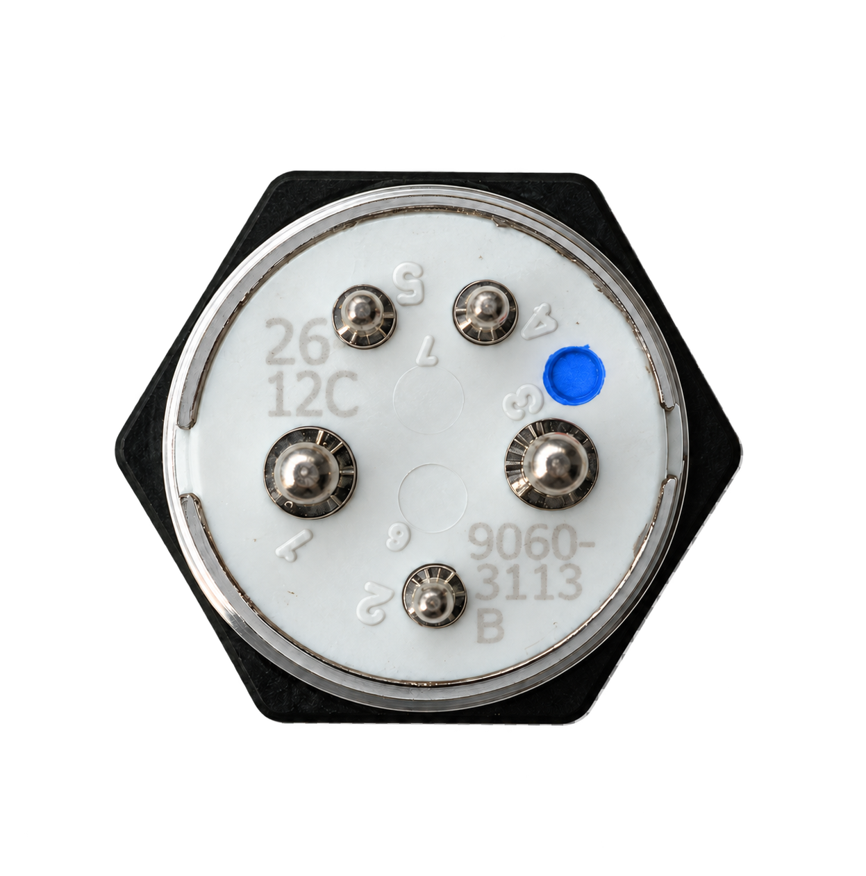
Selected plug diagram
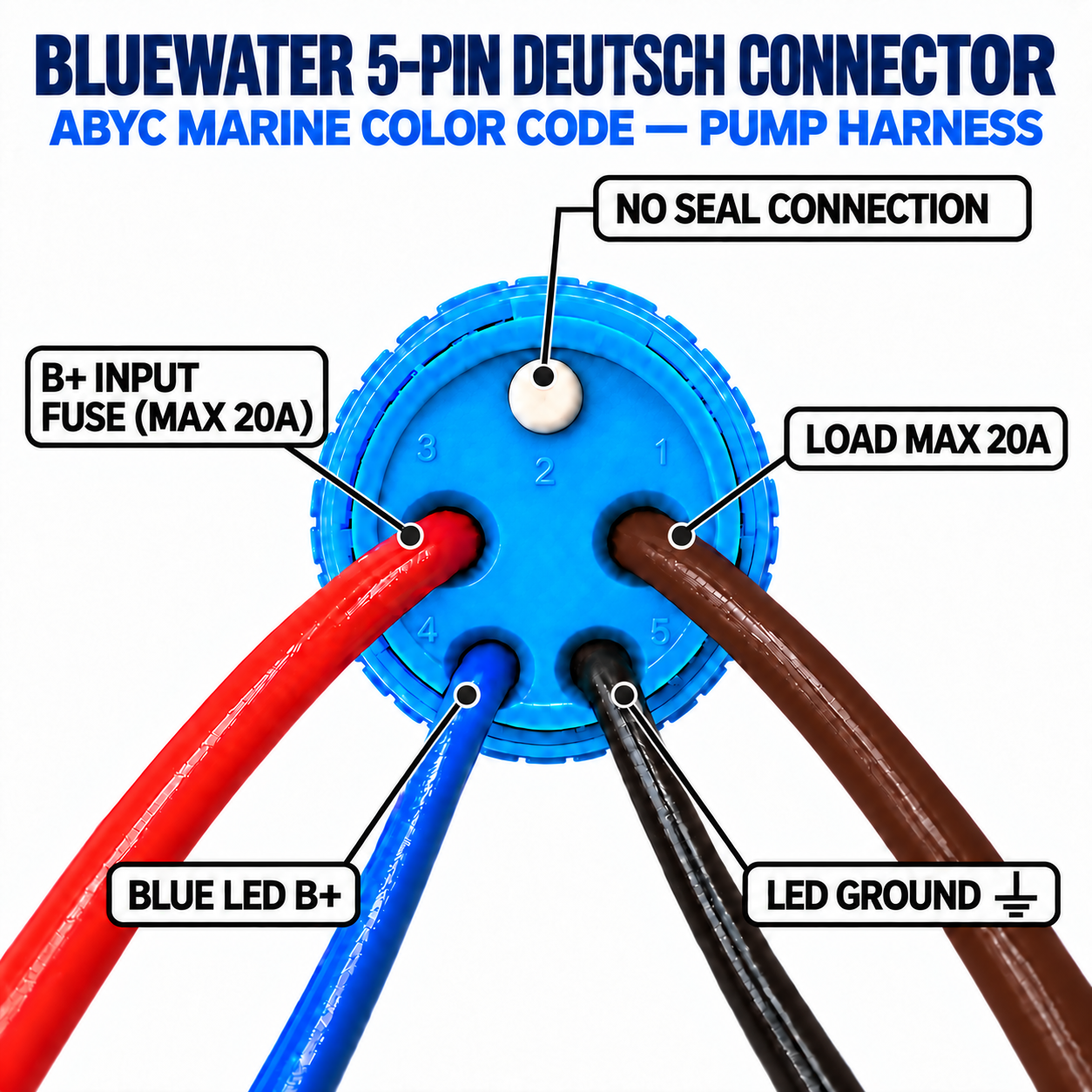
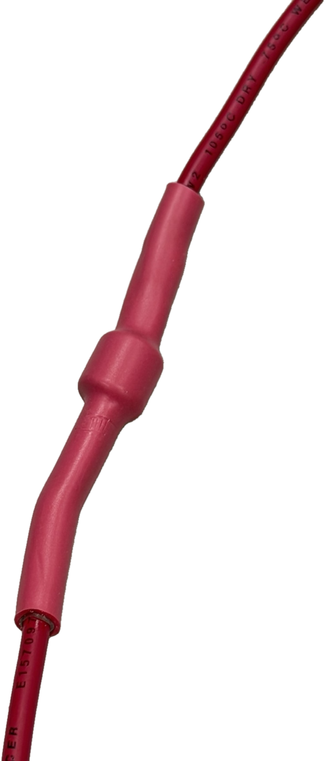
For any switch used with a bilge pump, IDIA installs a diode on the red input wire to prevent backfeed from the automatic float-switch circuit.
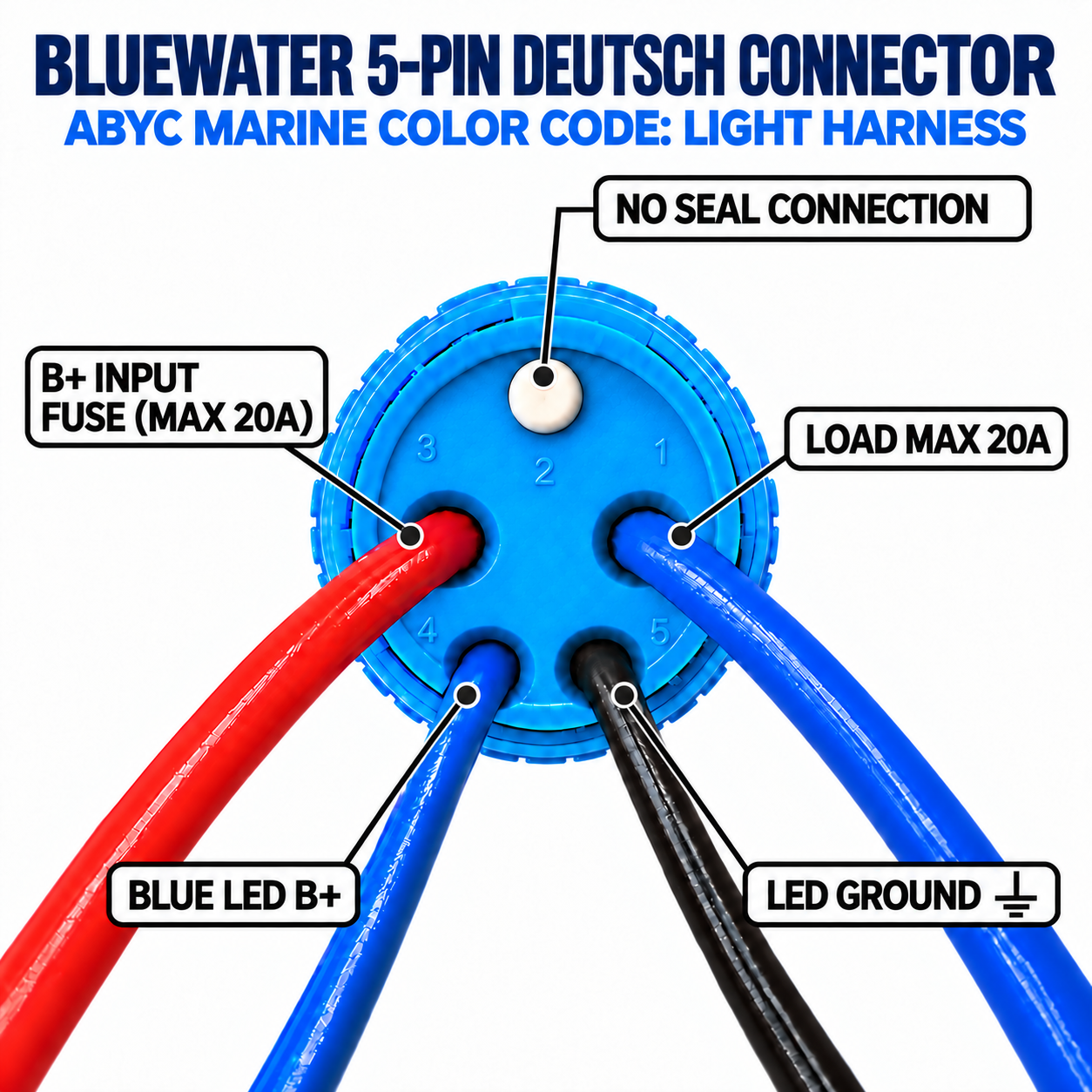
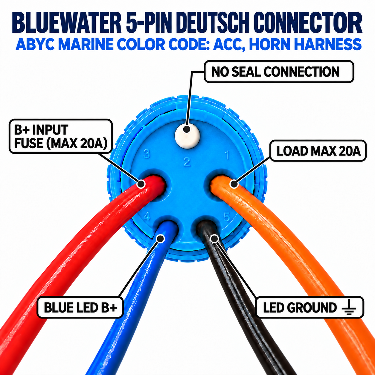
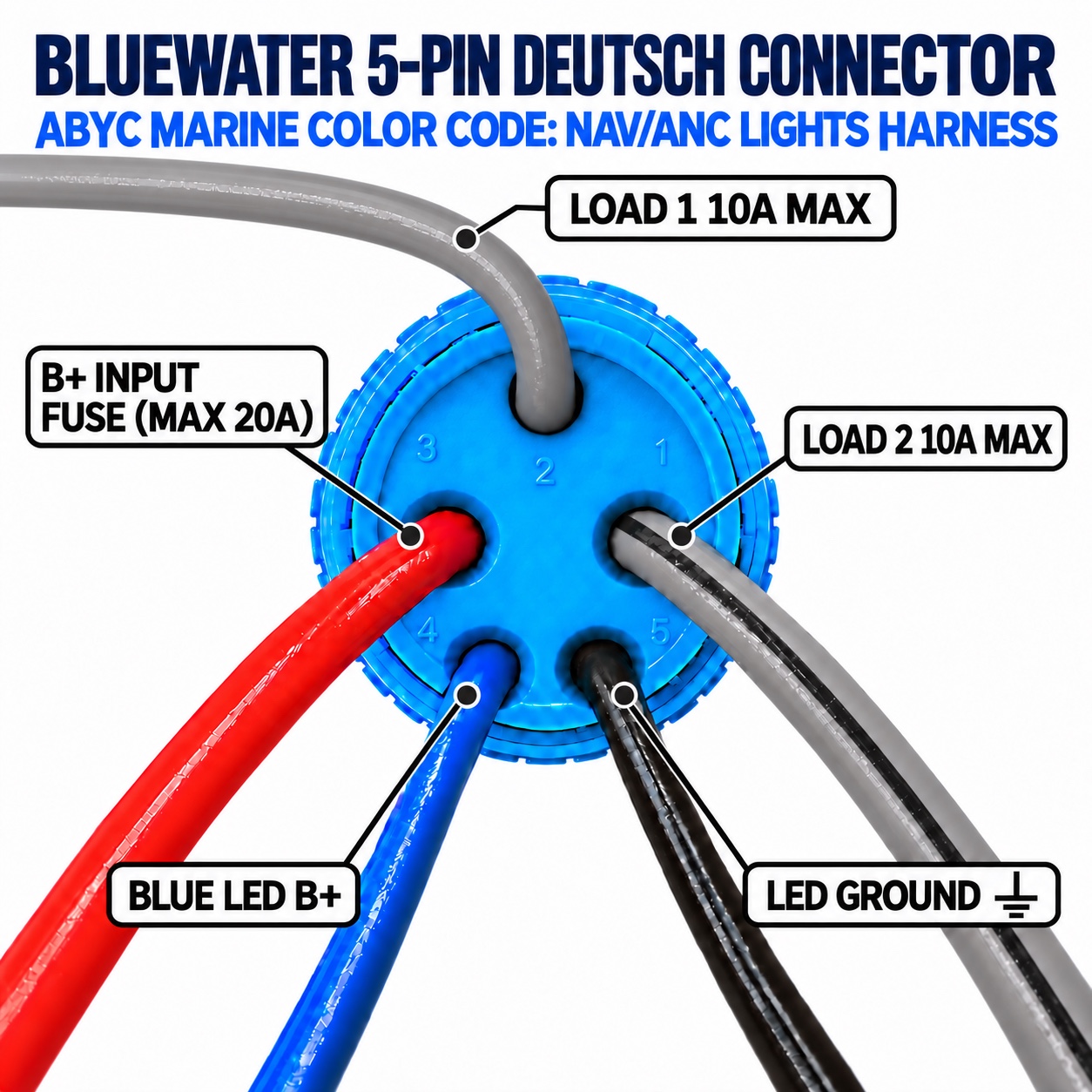
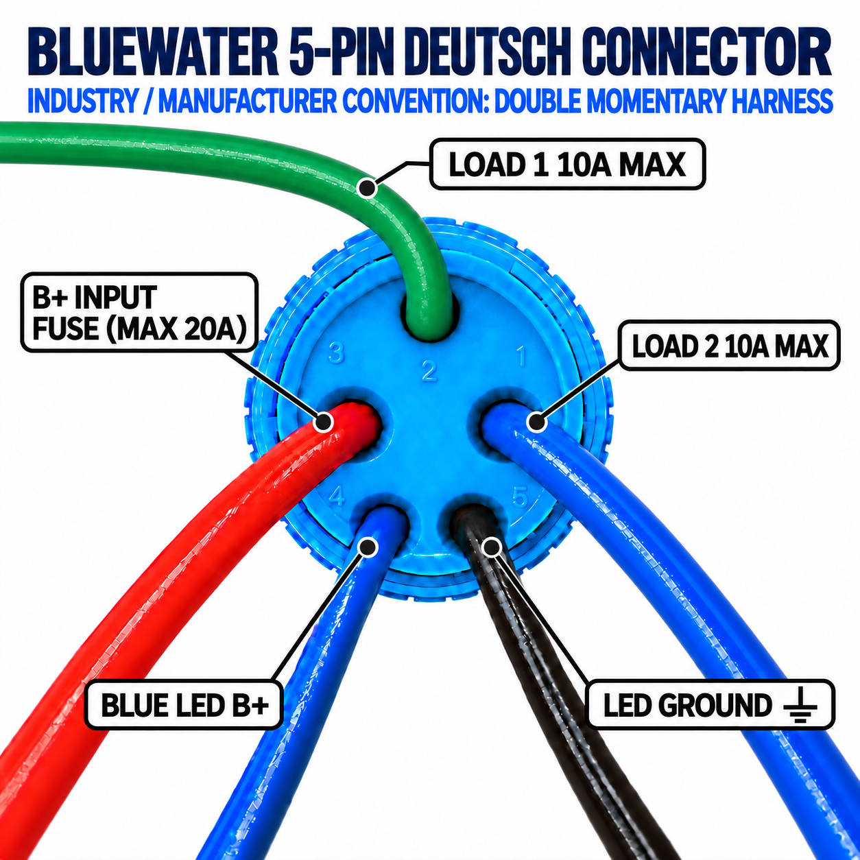
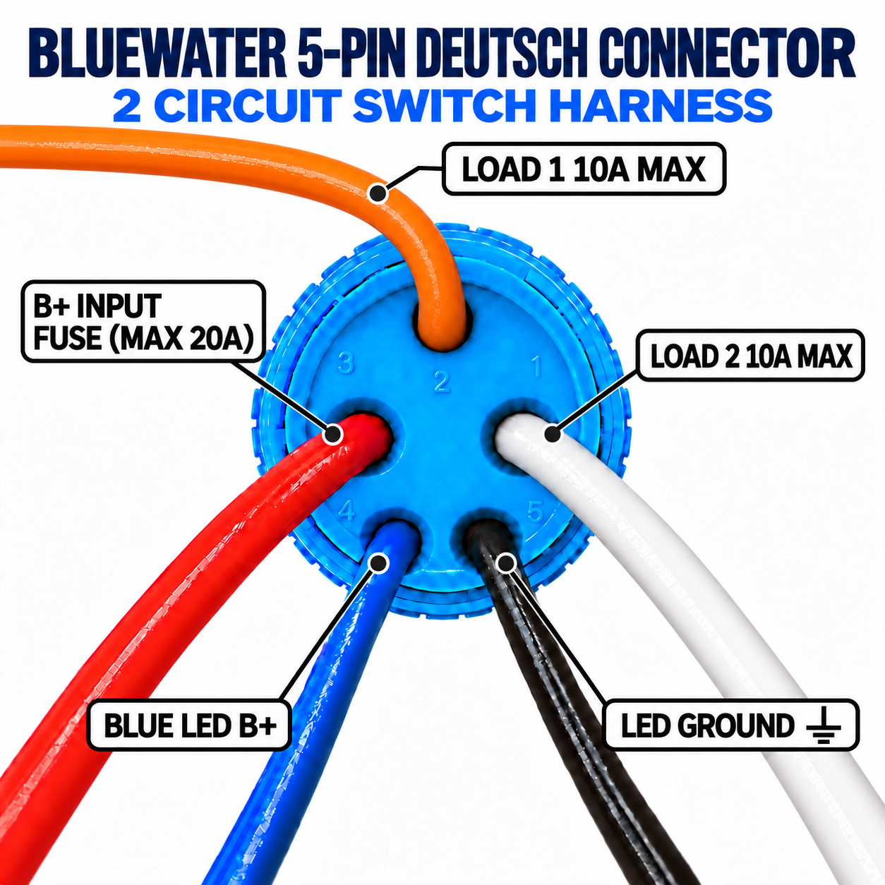
These two plugs work as a matched directional pair for compatible trim-tab, windlass, tilt, and reversing-motor controls.
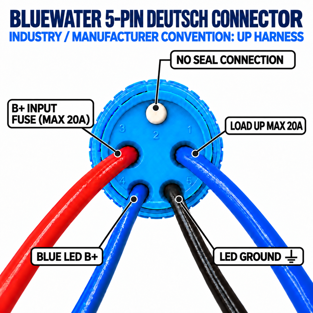
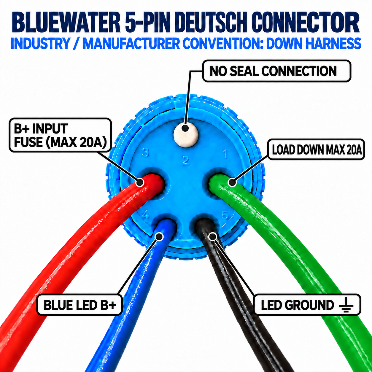
Disconnect power before servicing. These diagrams are connection references for IDIA INC harnesses; verify circuit requirements, manufacturer wiring instructions, and overcurrent protection for the specific vessel and installed equipment before energizing.
Save the PDF with the vessel documentation or print this QR code for the panel, harness packaging, or customer invoice.
Download customer PDF